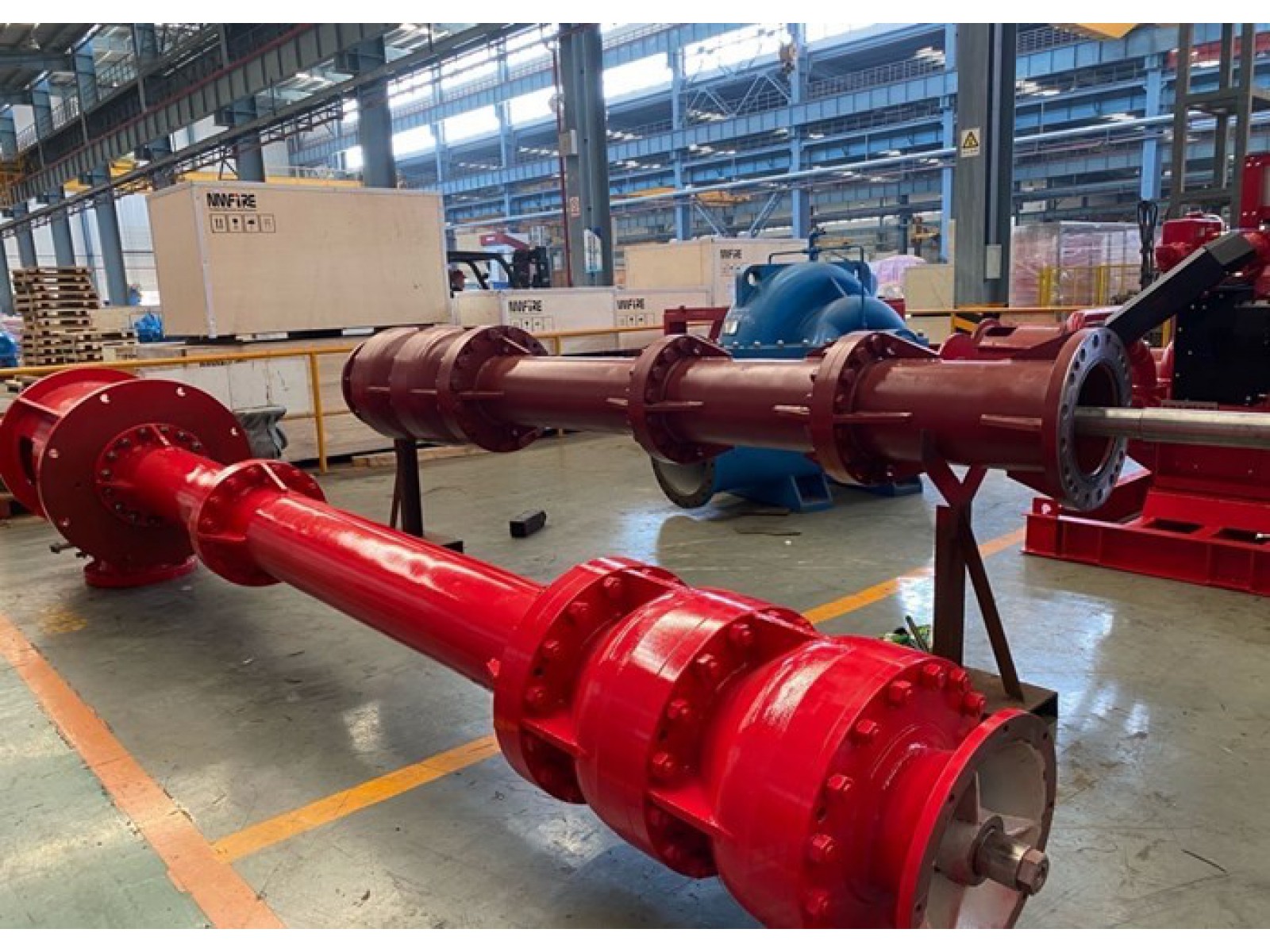
NFPA20 Standard Mutil-stage Vertial Turbine Fire Pump Capacities Up To 10,000 GPM For Firefighting Use
Standard and Range
Standards
NFPA20, UL, FM, EN12845,CCCF
Performance Ranges
UL : Q: 250-5000GPM H:80-300PSI
FM: Q: 250-5000GPM H:80-300PSI
CCCF: Q:15-300L/S H:0.60-2.0Mpa
NFPA20: Q: 250-5000GPM H:80-300PSI
How It Works:
The vertical turbine pump is normally driven by an AC electric induction motor or a diesel engine via a right angle drive. The end of the pump consists of a rotating impeller that is joined to a shaft and guides the well water into a diffuser casing known as a bowl.
Pumps with multi-stage arrangements use several impellers on a single shaft to generate higher pressure that would be required for pumping water from deeper wells or where higher pressure (head) is required at ground level.
A vertical turbine pump works when water comes through the pump from the bottom through a bell-shaped device known as a suction bell. The water then moves into the first stage impeller, which increases the velocity of the water. The water then moves into the diffuser casing directly above the impeller, where the high velocity energy is transformed into high pressure. The diffuser casing also guides the fluid into the next impeller located directly above the diffuser casing. The process goes on through all the stages in the pump.
After leaving the diffuser casing, the water passes in a vertical column pipe and rises toward the surface. The rotating shaft within the column is propped at 3 to 5 foot intervals using sleeve bushings that are set within the column and they are lubricated by the water as it moves past them. The pump also has a discharge head at the surface which allows the flow to change direction toward the discharge pipe. An upright standing high thrust A.C. motor is fitted above the pump’s discharge head.
ประตูน้ำเหล็กหล่อ : ลิ้นยกแบบรองลิ้นโลหะ สำหรับงานประปา
CASR IRON GATE VALVE – METAL SEATED FOR WATER SERVICES
MODEL (DN-CI-MS)
TIS 256 PN 6, 10, 16
TIS 432 PN 6, 10, 16
DIN 3352 PN 10, 16
BS 5150 PN 6, 10, 16
BS EN 1171 PN 6, 10, 16
Size DN80-1200 mm.
ประตูน้ำ (Gate Valve) เหล็กหล่อใต้ดิน ชนิดลิ้นยกแบบรองลิ้นโลหะ มอก.256
ประตูน้ำ (Gate Valve) เหล็กหล่อใต้ดิน ชนิดลิ้นยกแบบรองลิ้นโลหะ สำหรับงานประปา มอก.256
วาล์วได้ผลิตและทดสอบตามมาตรฐาน BS 5150 PN10/16/25, BS EN 1171:2002, BS EN 1074-2, TIS 432 PN 6 / 10 / 16 และสอดคล้องกับข้อกำหนดของ MSS-SP-70 class 125 / 250 ใช้งานได้กับทั้งน้ำ, อากาศและไอน้ำ
ตุณลักษณะ
- ตัวเรือนเป็นเหล็กหล่อ
- ปลายประตูน้ำ สามารถเป็นหน้าจาน, เกลียวและปลายเรียบ
- หน้าจานสามารถเจาะให้เข้ากับ ANSI B16.1, ANSI B16.5, BS4504, BS10, BS EN 1092-2, BS 4772, AS2129, DIN, JIS และอื่น ๆ
- เลือกตัวขับได้หลากหลาย ตามที่ต้องการเช่น พวงมาลัย, แป้นประแจขันหรือ cap, พวงมาลัยโซ่, เฟืองตรง, เฟืองดอกจอก, นิวเมติก, ไฮดรอลิก และไฟฟ้า
Fire Pump Controller UL FM standard for Jockey Pump Type
You have decided to reduce the risk of fire damage to your facility by installing a UL, ULC listed fire pump system. Your next decision is which system to purchase.
You want a fire pump that is proven in installations worldwide. Manufactured by an professional with vast experience in the fire protection field. You want complete service to field start-up. You want a
Engine Controller Fire Protection UL FM
Providing Pumping Solutions TONGKE Can Fulfill Your Requirements:
Complete in-house fabrication capabilities
Mechanical-run test capabilities with customer furnished equipment for all NFPA standards
Horizontal models for capacities to 2,500 gpm
Vertical models for capacities to 5,000 gpm
In-line models for capacities to 1,500 gpm
End suction models for capacities to 1,500 gpm
Drives: electric motor or diesel engine
Basic units and packaged systems.